Theory and Application of Power Factor Testing Article
Power Generation Vs Electrical Testing
Why do we want to see power factors in the 0.0% to 2.0% range (0.0 to 0.02) when analyzing from an electrical testing point of view? Why do we want to see power factors in the 90% to 100% (0.9 to 1.0) range when analyzing from a power generation point of view? These questions are not often asked and they are questions that many people can not answer. However, once an explanation is given and you are made aware of the correlation between the two, it should help give you a better overall understanding of power factor.
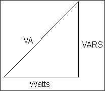
The answer lies within basic electrical theory. First, let's look at the power generation point-of-view. As stated, we already know a high power factor is desired. The closer to 100%, the more "efficient" the generating system. The easiest way of approaching this is by using the power triangle. There are two things we know for certain about electricity: it cannot be seen and it cannot be touched. The only things we have to represent electricity are numbers, but the power triangle gives us another visual means of representing electrical quantities. The power triangle appears like this:

Let's give a quick review of resistive, reactive, and total power, the parameters of the power triangle. Resistive power is the desired component and is considered to be the DC portion of the power triangle. In layman's terms, its unit is given in Watts and it is what we use for everyday electrical energy.
Reactive power is the unwanted portion of the power triangle (power generation being the consideration) and is considered to be the AC component of the power triangle. The units are given as VARS, which stands for volt-amps of reactance. Reactive power is introduced into a system whenever there is a rotating sinusoidal source delivering energy. "Total" reactive power is either capacitive or inductive but not both. Why? Because mathematically, capacitive reactance is given as a negative parameter while inductive reactance is given as a positive parameter, therefore, the two cancel out each other. If there is more inductive reactance than capacitive reactance, the circuit is said to be inductive with a "lagging" power factor. The situation is vice-versa for a circuit that contains more capacitive reactance than inductive reactance. The circuit would then be capacitive with a "leading" power factor. When we use the terms leading and lagging, we mean the current waveform is either leading or lagging the voltage waveform. Ideally, to obtain a power factor of 100% (1.0), the voltage and current waveform would need to be exactly in phase.
The last component in the power triangle left to discuss is total power. The units for total power are given as VA, which stands for volt-amps. Volt-amps are defined as the total apparent power of the system with its value being the product of the system volts and the system amps. When viewing the power triangle, one can see that it is a right triangle, thus Pythagorean's Theorem must hold true. This in turn defines total power as being equal to the square root of the sum of the reactive power squared and the resistive power squared, as given by the formula below:

Remembering basic electrical theory, we know power factor = cosine theta. We also know cosine theta = adjacent / hypotenuse by trigonometric definition. From this, it is easy to see that power factor = Watts / VA, or the ratio of true to apparent power. There are many ways to define power factor; those previously mentioned are two of the most common.
When considering power factor from a power generation point of view, it is important to understand that generators are not rated in megawatts (MW), but are instead rated in mega-volt-amps (MVA). This is contrary to popular belief. As stated previously, watts are the portion of the power triangle used for energy consumption. This is referred to as "true power". The volt-amp portion of the power triangle (hypotenuse) shows how hard a generator must work in order to produce the relative amount of watts. As stated above, volt-amps are referred to as "apparent power". Utilities concern themselves with this for several reasons. One of the main reasons is the heating effect of the current on the generator insulation. For example, if a generator has to produce 100 MVA to get 90 MW worth of usable power (this will give a single phase power factor of 0.9), it will obviously have to create more total current than it would if the power factor was higher, such as 0.95. In other words, if the power factor were higher, the generator would not have to produce 100 MVA to get 90 MW worth of power. This would give a smaller magnitude of total current. One must remember that current is the source of heat, and heat is the main cause of insulation deterioration. Another cause for concern would be capacity. If a generator was rated at 100 MVA, it could deliver 100 MW with a power factor of 1.0 (practically unachievable). With a power factor of 0.95, it could deliver 95 MW (for a single-phase system), thus losing 5 MW of its capacity to generate revenue. In other words, that's 5 MW of power capacity for which the utility can not get paid.
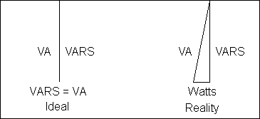
There are other ways of looking at the power factor model from a power generation point-of-view. Although it is sometimes used for voltage control, reactive power (the vertical component of the triangle) is somewhat unwanted. The ideal model would simply be a straight horizontal line as shown below. The straight horizontal line would represent a totally resistive system or a system where the inductive reactance and capacitive reactance are exactly equal. However, in reality the model will look more like the triangle shown below. This only makes sense, since the cosine of zero degrees is equal to 1.0. The smaller the angle, the better the power factor.

Now lets look at power factor from an electrical testing point-of-view. As stated earlier, we want the power factor for this situation to generally be in the 0.0% to 2.0% range. Why? The answer is quite simple if one really stops to think about it. The first thing we must consider is the model of a capacitor. Capacitance is defined as two conductors separated by a dielectric. All insulating systems can and should be modeled as an ideal capacitor. However, one must remember nothing is ideal in the practical sense. We are merely talking about a model. One conductor of this modeled capacitor is the current carrying conductor. The other conductor is ground. This could come in the form of the metal frame of a circuit breaker or the tank of a transformer. The dielectric portion of the modeled capacitor is obviously the insulation.
We already discussed the properties of capacitance to some degree. Now let's expand a little more. The ideal capacitor is considered to be a totally reactive circuit. In other words, there is no resistive component associated with the capacitor. Remember, we are talking about an ideal capacitor and in the real world there is nothing ideal. What this amounts to is some small amount of resistive current flow through all insulating systems. This resistive current is of the nano-amp to pico-amp range (for a good insulator), but nonetheless it is still present. The resistive current flowing through the insulation is the current responsible for keeping us from achieving a 0.0% power factor. If there were no resistive current flow, we would have a totally reactive test specimen.
How can current flow through porcelain, oil, paper, or any other insulating material? The scientific explanation for this is quite simple. It comes in the form of valence electrons. Remembering back to basic electrical theory, valence electrons are the electrons on the outer shell of the atom and are responsible for current flow. All materials known to man have valence electrons associated with their molecular structure. Some materials such as copper and silver obviously have many more valence electrons than other materials since they are considered to be the best conductors available. Other materials, such as the insulators mentioned above, have very few valence electrons associated with their molecular structure; therefore, they are poor conductors of electricity. Regardless of how poor of a conductor they are, they still conduct electricity, just in very small quantities. Thus, current does and will flow through all insulators including those mentioned.
With a totally reactive test specimen, you would have a straight vertical line when referencing the power triangle as shown below. However, in reality the model would look more like the one shown next to the ideal model because nothing is ideal in the world of electricity.

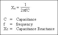
This only makes sense since the cosine of 90 degrees is equal to zero. We also know a couple of other characteristics about capacitors. For instance, we know an ideal capacitor is supposed to block DC current. Why? Just look at the equation below:

As the frequency approaches zero, the impedance approaches infinity. This should be obvious when one considers the application of Ohm's Law. The higher the impedance the smaller the current. What we are actually measuring is how un-ideal our capacitor or insulating system really is. In other words, how much of this resistive current is actually passing through the dielectric?
Test Set Operation
The power factor test set has a unique means of operating. While there are different manufacturers of power factor test equipment, all use the same principal of operation. The two most common power factor test sets in today's world are the AVO Delta 2000 and the Doble M4000. Both of these test sets use the principal of "zero reactance" to measure power factor. When we say zero reactance, we mean the reactive component (capacitance) is cancelled out by adding inductance into the test circuit. This is contrary to popular belief since many of the old null type test set models have dials labeled "Capacitance". In other words, there is a set of manual dials with numerals around their circumference. At the top of these dials, the word "Capacitance" is stenciled. These dials are rotated until a balance occurs on the null meter. What is actually happening? The test set is adding inductive reactance into the test circuit in order to cancel out the inherent capacitive reactance of the insulating system. Remember inductance and capacitance cancel each other out. There is a relatively large, tapped inductor (transformer) inside the test set that allows the addition of this inductive reactance. After all, what is an inductor? It is an insulated coil wrapped around a magnetic steel core. Sounds pretty much like a transformer to me. The test set uses this method of calculating the capacitance (how much inductance was added) of the test specimen. Once all the reactive power has been eliminated from the test circuit, the only portion left is resistive power (watts). This is a simple calculation; the test voltage (usually 10 kV) is multiplied by the remaining current, which is totally resistive, thus giving the watts loss value of the insulation. The test sets cannot distinguish between resistive and reactive current. The current initially seen by the test set is the total current or current found on the hypotenuse of the power triangle. The operation described above allows the test set to distinguish between the two different components of current.
Modes of Operation
The Power Factor Test Set comes with three basic modes of operation. These three modes of operation are referred to as the GST mode, the GST Guard mode, and the UST mode. GST stands for grounded specimen test while UST stands for ungrounded specimen test. While some of this may sound confusing, it should be understood that in application, it is actually a fairly simple concept.
When considering these different modes of operation, we have to understand what conductors (test leads) are associated with each mode. There are four different leads that protrude from the test set and connect to the test specimen. Of these four leads, one is the high voltage output lead. The high voltage output lead actually has nothing to do with any specific mode of operation. Of the remaining three, one is the ground return lead (GST) and the other two are the red and blue UST leads. This is where the confusion can start. Of the two UST leads, only one is actually used in over 95% of the practical application. So in order to avoid confusion for the novice, we recommend that only one of these UST leads be connected to the test set.
What all this amounts to is really quite simple. There are two paths of leakage current returning to the test set. One path is considered to be the ground path. Obviously, this would read the current returning on the ground lead (GST). In other words, the GST Guard tests read all the current leaking to ground only. The test set is guarding out the red or blue lead. Remember the UST lead (red or blue) still has current flowing on it, but is not being read by the test set in the GST Guard mode. The other path of leakage current returning to the test set is obviously the red or blue UST lead. The UST lead is returning leakage current to the test set that is not flowing to ground. Examples of this would be the leakage between the high side winding and low side winding of a transformer or the current leaking between the line side and the load side of an open circuit breaker. When the UST test is performed, the only current being measured by the test set is the current flowing on the red or blue lead. The ground leakage is still present. It just isn't being measured by the test set.
The last mode of operation to discuss is the GST mode. Some like to refer to this as the GST no guard mode. When this mode of operation is selected, both leakage paths (ground lead and the red or blue lead) are being read by the test set. This gives the overall condition or power factor of the test specimen. When the GST test is performed, the current, watts loss, and capacitance parameters of the UST and GST Guard tests should algebraically sum to equal the same parameters in this GST test. This only makes sense, since we are still reading the same two leads. The difference is we are reading them together instead of reading them separately. This provides a good check of the test results. The sum of the UST and GST guarded parameters should equal the GST parameters. If this is not the case, then either the test set is malfunctioning or there is the age-old problem of operator error being introduced.
It should be easy to see from the previous discussion that understanding the modes of operation is not as hard as it first appears. We are simply reading leakage current back to the test set on each lead individually and then with the sum of the two together. Hence, there are actually only three modes of operation one should have to understand.
