Ground Rules by John Cadick: The Per Unit System (Part 2)
 By John Cadick, P.E., Cadick Corporation
Overview
Last week I developed some of the fundamental formulas for the per unit system. This week I'll develop just one more formula, and then work a couple of simple, but illustrative examples. Consider Figure 1:
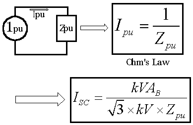
Figure 1 - Development of Equation (1.4)
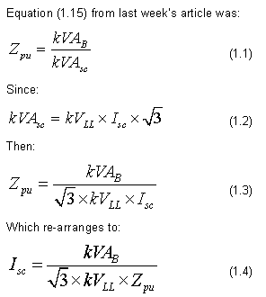
The following two examples show how per unit can be used to calculate short circuit currents. The first example is over-simplified, but it does illustrate the method.
Example #1
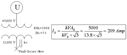
Figure 2 - Example #1 assuming the utility is infinite
Solution:
First we change the transformer percent impedance to per unit impedance:

An infinite source for the utility supplies means that it has zero impedance. Since the kVA base for the transformer is its full load of 5000 kVA, equation 1.4 for the fault location can be written as:

Example #2
A more realistic example assumes that the utility does have some impedance. For example, assume that the utility impedance limits a short circuit on the transformer primary to a maximum of 200,000 kVA. Figure 3 illustrates:
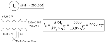
Figure 3 Fault analysis assuming non-infinite utility
Since the utility has an impedance, it will limit the fault current flow and must, therefore, be added to the transformer impedance to calculate the actual fault current. First, the utility per unit impedance needs to be calculated. To do this, we assume that the utility base kVA is 200,000. From our per unit formulas this means that:

Using Equation 1.10 (from last week's column), we can convert the utility impedance to the transformer base. This must be done so that the two can be added:

Note that the voltage base is not used in this case since the transformer impedance is the same referenced to either side. If we ignore the phase angle difference between the two impedances, we can calculate the short circuit current by adding the transformer plus the utility:

Example #3
In example 2, we assumed that the utility impedance and the transformer impedance are at the same angle. This would rarely be true. How are the results affected if we assume that the utility X/R ratio is 10 and the transformer X/R ratio is 7. X/R ratio is equal to the tangent angle by which the current lags (or leads) the voltage. In other words the impedance angle is the inverse tangent of the X/R ratio. Thus:
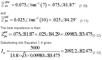
Obviously this inclusion makes only a very small difference. A fairly typical result when working at medium and higher voltages.
Conclusion
The per unit system allows the analysis of very large power systems, even when multiple voltage levels are involved. After converting the entire system to a common set of "bases" the engineer may then go about calculations in the same way that would be accomplished using Amperes, Ohms, and Volts.
Questions? Comments? Send them to editor@electricnet.com.
A registered professional engineer, John Cadick has specialized for three decades in electrical engineering, training, and management. In 1986 he created Cadick Professional Services (forerunner to the present-day Cadick Corporation), a consulting firm in Garland, Texas. His firm specializes in electrical engineering and training, working extensively in the areas of power system design and engineering studies, condition based maintenance programs, and electrical safety. Prior to the creation of Cadick Corporation, John held a number of technical and managerial positions with electric utilities, electrical testing firms, and consulting firms. Mr. Cadick is a widely published author of numerous articles and technical papers. He is the author of the Electrical Safety Handbook as well as Cables and Wiring. His expertise in electrical engineering as well as electrical maintenance and testing coupled with his extensive experience in the electrical power industry makes Mr. Cadick a highly respected and sought after consultant in the industry. (Back to top)
