
Ground Rules by John Cadick: Marine electrical safety
 By John Cadick, P.E., Cadick Corporation
Table of contents
Overview
Risk Assessment
Safety Related Design Recommendations
Safety Related Work Practice Recommendations
Ship=s Force Safety Related Training Recommendations
Overview (Back to top)
Electrical power systems on shipboard have increased in voltage level as well as complexity. These changes require a fresh look at the issue of electrical safety. Distribution systems on vessels are now weighing in at 6600 Volts instead of 450 Volts. This means that virtually all procedures must be reworked to accommodate the increased hazard levels presented by such voltages. While intended primarily for application to medium voltage (above 1000 Volts and less than 100,000 Volts, the general concepts covered in this bulletin can and should be applied to the entire electrical system. This bulletin is divided into five (5) basic sections as follows:
- Overview
- Risk Assessment
- Safety Related Design Recommendations
- Safety Related Work Practices Recommendations
- Ship=s Force Safety Related Training Recommendations
- The risk assessment discussed in Section 2
- The collective experience of the key members of the Cadick Corporation research team in both land-based and marine facilities.
- The experience gained by Cadick Corporation during startup and training of personnel on-board the Coast Guard Ice-breaker Healy (WAGB - 20).
Note that the recommendations given in this report are intended primarily for application in the medium voltage sections of a marine power system; however, the general principles will apply equally to 450 Volt gear. The principle differences between the older, low voltage systems and the more modern medium voltage systems lies in the energy level and the degree of current flow during contact (shock) or arcing events. Because of the greater amount of energy in the medium voltage system, more stringent requirements must be put in place for personnel insulation and flash protection.
Risk Assessment (Back to top)
Medium voltage electric distribution systems are not new. Since safety equipment and procedures for such systems have long been established, the primary purpose of this analysis is to estimate the increased electrical safety risks involved when medium voltage electric distribution is applied on board a ship.
There are many activities that bring personnel into close proximity with medium voltage distribution systems, and for which electric safety is paramount. These activities are summarized below:
- Switching. The act of energizing or de-energizing electrical facilities. This may be done routinely and during emergencies, as when:
- de-energizing loads and portions of the system
- restoring service to facilities
- transferring load from one source to another
- clearing electrical faults
- isolating electrical faults
- recording measurements and relay targets
- measurement of electrical quantities
- live maintenance and/or troubleshooting
- equipment maintenance and overhaul
- equipment cleaning
- protective device testing and calibration
- breaker trip testing
- insulating testing
- safety voltage measurement
- replacement of fuses
- racking in or out of breakers
Activities in the presence of electrical conductors that are known to be energized.
Activities in the presence of conductors that are known to be de-energized. It is assumed that the de-energized status of equipment and conductors has been verified in accordance with appropriate safety procedures including lockout/tagout, and equipment is grounded and short circuited to create an equipotential zone.
Activities in the presence of conductors that may be energized. The status of conductors has not been verified to be de-energized.
Although routine maintenance is normally expected to be performed while the ship is in port, emergency maintenance and troubleshooting can be required at any time. Therefore we expect and assume that such activities will occur at roughly the same frequency as in land based medium voltage electric power systems.
Furthermore, the risk of equipment misoperation and failure are expected and assumed in this analysis to be essentially the same as land based systems. There is nothing a marine power system that would indicate a drastic difference in expected component performance. Of course, this assumes normal operations. Activities during combat or emergency operation are unpredictable and subject to temporary repeal of normal procedures.
While there is more use of power semiconductors in marine systems than in conventional medium voltage distribution systems, this technology is confined to power conversion modules, which create multiple DC and variable frequency AC voltages. For the sake of a conservative approach, the application of such technology is assumed to have no impact on the overall safety of personnel. Since fast acting semiconductor power supplies can greatly reduce the electric arc hazard, revisions may be required as system designs mature.
Those differences between land based electric distribution and shipboard medium voltage distribution having the greatest impact on electrical safety are as follows (in the order of impact):
- The clearances are smaller. The space available for personnel activities is greatly reduced.
- Personnel are more likely to be inexperienced with medium voltage equipment, only because medium voltage distribution has not until recently been generally applied aboard ship.
- There is more metal surrounding work spaces. This makes it easier to establish equipotential surfaces and thus reduce step and touch potentials.
|
Hazard |
Description |
Impact of Shipboard Application on the Likelihood of Hazard |
Impact of Shipboard Application on the Consequence of Hazard |
|
Shock |
The hazard is severe injury up to and including electrocution, when electrical current comes in contact with the human body and even is conducted through it. |
Maintaining proper clearance from energized conductors may be much more difficult in a confined work space. Contact with these conductors is therefore more likely. Inexperience with the tools and procedures of medium voltage electrical systems may increase further the likelihood of mishap. This may be offset somewhat by the fact that equipotential zones are much easier to set up on shipboard. There is nothing in the marine application or IPS design that makes shock inherently morelikely. The likelihood of a shock hazard occurring is, in reality, the likelihood of an accident. Table 2 discusses the likelihood of accident more thoroughly. |
There is nothing in marine applications or the description of the IPS indicating any change in the severity of the consequences of contact with electricity. |
|
Arc |
Electrical arcs of sufficient energy can cause fatal burns at distances of up to 8 feet or more. Even if the direct burns are not immediately fatal, clothing can be ignited and lead to fatal secondary burns. |
Because of the relatively more compact construction of the IPS, electrical arcs may be marginally more likely to occur. |
The amount of damage experienced diminishes as the square of the distance from the arc. Twice as far means one fourth the damage. Personnel forced into closer proximity with the arc will experience geometrically increased thermal damage. |
|
Blast |
An electric arc superheats the air instantaneously. The expansion of the air can reach pressures of 200 pounds per square foot, sufficient to explode switchgear, push over concrete walls, and turn sheet metal into shrapnel. |
Since arcs may be marginally more likely, blast will also be more likely. |
Confined work areas force personnel into closer proximity with the force of the blast. Personnel are at the same time more likely to be exposed, and will suffer greater from the exposure. Additionally, the confined area can have the effect of enclosing and concentrating the effect of the blast. |
Next we look at the categories of activities, and the impact of marine application on their safe accomplishment. Table 2 summarizes:
|
Activity |
Impact of Shipboard Application on the Likelihood of Accident |
Impact of Shipboard Application on the Consequence of Accident |
|
Switching |
The equipment itself is not more (or less) likely to fail or misoperate. There is some increased likelihood of misoperation due to the inexperience of operators and/or to the closer quarters in which they must work. |
The consequences of an electrical safety accident are the same as with land based systems, namely: exposure to the hazards of shock, arc, and blast. The impact of marine applications on these hazards is described in Table 1. |
|
Activities in the presence of electrical conductors that are known to be energized |
Maintaining proper clearance from energized conductors may be much more difficult in a confined work space. Contact with these conductors is therefore more likely. Inexperience with the tools and procedures of medium voltage electrical systems may increase further the likelihood of mishap. |
|
|
Activities in the presence of conductors that are known to be de-energized. |
Inappropriately applied or failing grounds are not more (or less) likely aboard ship. Accidental re-energization is likewise not more (or less) likely in marine applications. Exposure to voltage is slightly reduced by the improved quality of established equipotential surfaces. |
|
|
Activities in the presence of conductors that may be energized. |
It is not more (or less) likely that energized conductors are undetected in marine applications. However, maintaining proper clearance from these conductors may be much more difficult in a confined work space. Contact with these conductors is therefore more likely. Inexperience with the tools and procedures of medium voltage electrical systems may further increase the likelihood of mishap. |
A quantitative assessment involves, at least initially, a judgement of relative magnitudes. The following magnitudes were assumed in this analysis. While they are based on our judgement and experience, the effect on the overall analysis of assuming different initial values will be readily apparent.
Table 1 & 2 together show that the impact on the likelihood of an electrical safety incident is dominated by the impact on the likelihood of an accident, while the impact on the consequences of an incident is dominated by the impact of the electrical hazards. This simplifies the next stage of analysis: the quantitative assessment.
Keep in mind that our goal is not to evaluate the absolute risks of various activities, or even compare them. We are assessing the increase in those risks as a result of the marine application.
Table 3 shows the assignment of magnitudes.
|
Likelihood |
Shock |
Arc |
Blast |
|
Switching |
1.2 |
1.2 |
1.2 |
|
Energized |
1.5 |
1.5 |
1.5 |
|
De-energized |
0.8 |
0.8 |
0.8 |
|
May be Energized |
1.5 |
1.5 |
1.5 |
|
Consequence |
Shock |
Arc |
Blast |
|
Switching |
1.0 |
2.0 |
3.0 |
|
Energized |
1.0 |
2.0 |
3.0 |
|
De-energized |
1.0 |
2.0 |
3.0 |
|
May be Energized |
1.0 |
2.0 |
3.0 |
Looking at the top part of Table 3:
- The impact on the likelihood of a safety incident for activities in the presence of energized conductors, and conductors that may be energized, is the same, and given the highest value.
- The impact on the likelihood of an incident when switching is somewhat less, though there is still an increased likelihood over land based systems. This not because the equipment is more likely to fail or misoperate in a marine application; rather, it is because the operators likely to be less experienced.
- The impact on the likelihood of a electrical safety incident when conductors are de-energized is to make these activities somewhat safer on board a ship, due to the improved quality of the equipotential surfaces. Recall that it is assumed for these activities that the de-energized status of equipment and conductors has been verified in accordance with appropriate safety procedures, and safety grounds and short circuits have been applied to create an equipotential zone.
- The consequences of electrical shock are unaffected by marine application.
- The full integer multiplier for the impact of marine application on arc damage is justified by the geometric relationship between proximity and resultant damage. A reduction of 29% in the distance between the arc and the operator will double the thermal damage.
- Blast has a higher multiplier due to the added effect of confined areas to concentrate the blast and magnify its impact.
|
Activity |
Risk Relative to Land Based Systems |
Safety Notes |
|
Switching
|
240% more risk, due to reduced clearances and confined work spaces, and inexperience of personnel. |
Personnel must be qualified and familiar with the equipment. Risk can be mitigated with focused training. Only one person should be in the switchgear compartment to perform switching. Another person should be outside, with a remote communications device. Second person is more likely to survive a blast and initiate appropriate rescue. Personnel need to strictly adhere to proper safety procedures, especially with respect to body and face protection, and positioning that limits as much as possible exposure to heat, molten metal, and flying debris. |
|
Activities in the presence of electrical conductors that are known to be energized
|
300% more risk, due to reduced clearances and confined work spaces, and inexperience of personnel. |
Live maintenance is the riskiest behavior in this category, and should be avoided unless absolutely necessary. Comments above apply as well. Test equipment must be operated in strict adherence to safe procedures. |
|
Activities in the presence of conductors that are known to be de-energized.
|
160% more risk, due to reduced clearances and confined work spaces, and inexperience of personnel, mitigated somewhat by better equipotential surfaces. |
It is assumed that the de-energized status of equipment and conductors has been verified in accordance with appropriate safety procedures, and safety grounds have been applied as appropriate. Grounding procedures must be adhered to strictly, to establish an equipotential zone. Facility must provide appropriate lugs for attachment of ground clamps. |
|
Activities in the presence of conductors that may be energized. The status of conductors has not been verified to be de-energized
|
300% more risk, due to reduced clearances and confined work spaces, and inexperience of personnel. |
Racking in and out of breakers is the riskiest behavior in this category, as the visible open is not designed to interrupt load or fault current. Comments under switching apply. Test equipment must be operated strictly according to safe procedures. |
While not materially affecting the final results, the composite risk value is obtained by taking a numerical average of the shock, arc, and blast hazards. From this we conclude that, nominally, medium voltage electric power distribution systems are between 1.6 and 3 times more hazardous to operating personnel when applied aboard a ship. Not all activities are impacted equally, and Table 4 shows the increased risk for each activity.
Safety Related Design Recommendations (Back to top)
 Based on the three criteria identified in the Overview section of this report, the following design criteria should be considered in a medium voltage marine power system.
1. Arc-resistant switchgear
Arc resistant switchgear is electrical gear that is, by design and construction, less likely to incur electric arcs and more capable of reducing the consequences of electrical arcs. It does so as identified in Figure 1. At the present time at least three (3) major manufacturers are constructing arc-resistant switchgear.
All portions of a marine power system should be manufactured using arc-resistant switchgear techniques.
2. Permanently mounted safety grounding connectors
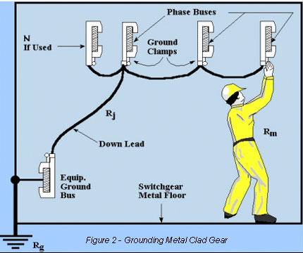
Electrical safety grounding is one of the premiere methods used to prevent injury in the event that a de-energized system should become unexpectedly re-energized. The basic purpose of safety grounding is to create a zone of equalized potential (equipotential zone) surrounding workers so that, in the event the system becomes inadvertently energized, workers are fully protected and surrounded by metal conductors. Figure 2 illustrates the basic concept of safety grounding as it applies to metal clad gear similar to that being used in the modern marine systems.
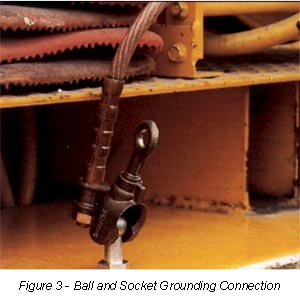 One of the great difficulties in applying safety grounds is the wide number of clamp styles required by the various shapes and sizes of electrical bus work. This problem can be resolved by the use of permanently mounted clamp connection points. These devices, as illustrated in Figure 3, are stock items available from a number of safety equipment manufacturers.
Note that the connection device is similar in appearance to the commonly used bumper hitch. The device is permanently bolted to the electrical bus in appropriate locations, thus providing a secure connection point for the electrical safety grounds. Naturally the connection devices must be selected based on the specific system parameters such as available fault current, space available, and so on.
3. Use of current, voltage, and control test switches
During commissioning tests on the US Coast Guard Cutter Healy, we observed that testing and calibrating instruments was made extremely difficult because no connection points were available.
Several manufacturers make test connection plugs and/or switches for protective relays and other types of system instruments. These devices are usually mounted on the same panel that holds the instrument. To apply voltage or current for testing purposes, the technician need only insert the appropriate test lead.
Note that using this type of equipment eliminates the hazard normally associated with opening current transformer circuits since the test device is provided with a mechanism that automatically bypasses the current transformer circuit.
4. Clear and consistent labeling of all system components
Because of the bidding system employed by the Federal Government, different parts of the power system may be provided by different manufacturers. Prior to issuing specifications to manufacturers, designers should insure that all equipment marking and labeling standards are clearly indicated. During commissioning of the Healy, we observed that different modules used different labeling techniques. This made identification of the equipment and the test results very difficult. It will be equally difficult for ship=s force during operations.
5. All additional requirements as described in CFR Title 29 Parts 1910.302-308, and National Fire Protection Association NFPA 70E
CFR Title 29 Parts 1910.302-308 (OSHA Electrical Safety Design Standards) and the National Fire Protection Association NFPA 70E are among the electrical design documents used for land-based systems. Since these standards have proven track records, they should also be used by designers of the IPS system.
6. Other good practice design procedures which, while not necessarily required by regulatory standards, will provide the ultimate level of personnel safety. Such design items might include:
- Mimic bus designs on the front of all switchgear
- Color coding of cables to distinguish medium voltage (orange for example)
1. Required safety equipment for personnel (PPE)
- Rubber insulating equipment (rated for both low and medium voltage applications)
- Gloves with appropriate leather protectors
- Blankets
- Sleeves
- Gloves with appropriate leather protectors
- Insulating hard-hats
- Eye protection with UV protection
- Thermal protective clothing (Nomex, PBI, or Kermel recommended.)
- Insulated hand tools
- Safety rated voltage measuring instruments
2. Strict observance of clearance distances
OSHA standards, and more recently NFPA 70E, have clearly established the concept of approach distances. An approach distance is defined as how close a worker may approach an exposed energized conductor (or one whose energization state is unknown), without using extra safety equipment and safety related work practices. Figure 4 illustrates these clearance distances as defined in NFPA 70E. The clearance distances can be defined based on NFPA 70E Table 2-1.3.4 and/or suitable formulas during the specific safety design procedures for the electrical system. Key to these observances will be the use of appropriate procedures to determine what specific safety equipment is required to be allowed to break the various safety boundaries.
3. Establish clear-cut lockout/tagout requirements
Equipment should not be considered de-energized until it has been voltage measured, locked, tagged, and safety grounded. The lockout/tagout procedure is the principal element in this package. Basically the steps are as follows:
- De-energize the equipment using the appropriate breakers and/or control switches
- Apply safety locks and tags to the equipment in such a way that the gear cannot be re-energized without removal of the lock.
- Try to re-energize the equipment to verify that the locking procedure was successful.
- If exposure to electrical conductors will occur, make a three step voltage measurement to verify that the system is de-energized and no electrical energy is present.
- After the voltage measure is performed, apply electrical safety grounds as appropriate to the task at hand.
5. Use of team concepts
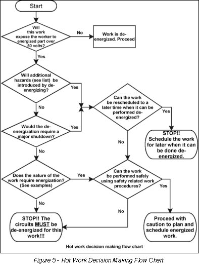
When working on circuits in excess of 1000 Volts which are, or may become, energized, we strongly recommend the application of the team concept. That is, work teams should be set up in teams of two, at a minimum. A summary of such activity is briefly described in Figure 5.
Ship=s Force Safety Related Training Recommendations (Back to top)
All ship=s force who are exposed to electrical hazards in excess of fifty Volts (50 V) to ground should be provided in depth, hands-on training experience in the following topics:
- Nature and characteristics of the electrical hazards
- Voltage Measurement techniques
- Lockout/Tagout
- Clearance distances
- Application of Safety Grounds
- Safe use of tools and equipment
- Electrical hazard recognition and avoidance
- Confined space electrical hazard avoidance
A registered professional engineer, John Cadick has specialized for three decades in electrical engineering, training, and management. In 1986 he created Cadick Professional Services (forerunner to the present-day Cadick Corporation), a consulting firm in Garland, Texas. His firm specializes in electrical engineering and training, working extensively in the areas of power system design and engineering studies, condition based maintenance programs, and electrical safety. Prior to the creation of Cadick Corporation, John held a number of technical and managerial positions with electric utilities, electrical testing firms, and consulting firms. Mr. Cadick is a widely published author of numerous articles and technical papers. He is the author of the Electrical Safety Handbook as well as Cables and Wiring. His expertise in electrical engineering as well as electrical maintenance and testing coupled with his extensive experience in the electrical power industry makes Mr. Cadick a highly respected and sought after consultant in the industry. (Back to top)