Distributed Redundancy

By Robert Bauer, Liebert Americas president
Contents
Information Needs Intensify: What Factors Affect Critical Data Integrity?
Determining Fault Tolerance: How Much is Enough Protection?
Rating the Options: "Traditional" to Distributed Redundancy
Isolated Redundant UPS
Parallel Redundant (N+1) UPS
1+1 Parallel Redundant UPS
Distributed Redundant Dual UPS Bus System
Distributed Redundancy: A Critical Part of the Business Plan
As the need for greater system availability intensifies across virtually every industry — from global banking to just-in-time manufacturing — network, IT, and other information systems managers are asked to guarantee an unprecedented level of computer uptime. To compound the problem, the platforms on which these critical applications reside have never been more vulnerable. They are often a mixture of leading-edge and aging technology and housed far from the protected environments sensitive electronics once enjoyed.
This white paper concerns the recently developed power protection system, distributed redundancy. Distributed redundancy ensures 100% power as it dramatically improves power availability, approaching the virtual 100% level. The unprecedented level of power protection is assured regardless of platform, application criticality, or downtime sensitivity — when even one hour per year of power system downtime is unacceptable. Moreover, distributed redundancy doesn't compromise any aspect of system management, from the ability to easily perform equipment maintenance to the ability to fit within an investment/liability budgetary ratio. What follows is an examination of factors that led to the need for this level of protection as well as a detailed discussion of the components that comprise distributed redundancy.
Information Needs Intensify: What Factors Affect Critical Data Integrity?
Four factors combine in today's enterprise to create a business threat:
- power reliability
- electric equipment sensitivity
- the advent of distributed processing
- reliance on information as a critical, if not primary, business function — creating the need for greater system availability.
Reliability is defined as the probability that some item will perform as intended for a specified period of time and under a stated set of conditions. It may seem as though power reliability is no longer an issue, particularly for U.S.-based organizations. Power outages long enough to notice happen only a few times a year. But in most parts of the country, power fluctuations occur at an average of nearly one a day. One daily fluctuation is enough to cause many "unexplained" system problems. Effects can include system and drive crashes, data transmission errors or shutdowns, server shutdowns and reboots, even premature component failure.
Micro-computers left the glass house as they became more tolerant of everyday office conditions. Unconnected, problems remained isolated. Today, high-speed computing and communications technologies across networks of every size are becoming the norm. So higher levels of sensitivity are creeping back into network hardware. An additional consideration: power fluctuations aren't the only problems out in the "real world." Heat, dust, vibration and people can bring down a network even if the power source is perfect.
Finally, the need for high availability is increasing at incredible rates, often approaching 100%. When the system goes down, the work place slows to a crawl or stops altogether. This is true across all industries, whether the organization is service-based or manufacturing. (Back to top)
Determining Fault Tolerance: How Much is Enough Protection?
Each year Contingency Planning Research (CPR) polls firms in various industries to identify the costs when vital networks go down for just one hour (Figure 1). Results range from a package shipping service with an hourly financial impact of up to $32,000 to an airline reservation center that tops out at a $112,000 loss per hour.

To identify the level of power protection right for your organization, you must first determine your acceptable level of fault tolerance. Fault tolerance encompasses not only how quickly the network can recover from a power failure, but also how much protection it needs against both "slow" and "fast" power failures. Two elements have been used to determine fault tolerance. The most common is the acceptable mean time between failure or MTBF. A less understood but perhaps a more relevant determiner of acceptable fault tolerance is represented by redundancy objectives as they apply to protecting the network.
Much has been published among business equipment suppliers and IS managers about MTBF. By definition, it is the average time before failure of an item under a specified set of conditions. The MTBF for critical support systems, such as UPSs, should be as high as 10 times the load MTBF.
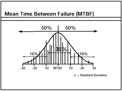
In and of itself, MTBF data has limited usefulness. By its very nature as an "average," it tends to obscure critical information. The most basic MTBF calculations assume gaussian (normal) data distribution, which can distort or ignore many of the real-world challenges your network may face. For these reasons and others, the MTBF characteristic alone should never be mistaken for a measure of availability; a predictor of risk failure prior to the calculated MTBF elapsed time; or an excuse to value one particular MTBF number over another.
Redundancy objectives can serve as much more realistic predictors of your necessary level of fault tolerance. These objectives are formed around the question: how much protection is enough? Redundancy objectives hold 7x24x365 as the operational goal; adhere to a flexible power distribution; and plan for maintenance and upgrades without shutdown.
If 100% availability seems too high for your system, consider what 99.9% availability translates into across user applications. One hour of unsafe drinking water. Two unsafe plane landings per airport per day. Twenty thousand incorrect surgical operations per week. Twenty-two thousand checks deducted from the wrong account every hour. (Back to top)
Rating the Options: "Traditional" to Distributed Redundancy
There are several levels of traditional configurations designed for power reliability and availability. However, many obvious and hidden factors affect the level achievable by these configurations.
Single Module. Single Module Systems are popular and perhaps the most well known. They are typically configured as:
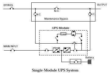
Single Module Systems provide adequate continuous power protection under certain conditions. The UPS must be a true on-line topology; a static bypass switch should be in place to provide the utility to the load in the event of a UPS transfer from its inverter; and the entire critical load demand for the facility should not exceed 1000kVA.
Disadvantages remain numerous and sometimes hidden among the statistics of an average MTBF of 100,000 hours. For example, there is only a 37% chance of achieving this MTBF figure. One reason may be the UPS itself. A UPS that has not been factory- or field-tested can actually reduce expected reliability by experiencing both infant mortality (e.g., failing soon after installation) and age-imposed mortality (i.e., factors that impact the longevity of the unit). Liebert's 600T, on the other hand, has a field-proven MTBF of >1M hours.
Another challenge with this configuration: the UPS has to be taken off-line for maintenance, service and IEEE battery testing as well. Therefore, it is obviously not available to the load at these times. A typical single module application would involve an information-intensive but not "critical" environment such as a hospital administration system (versus diagnostic systems).
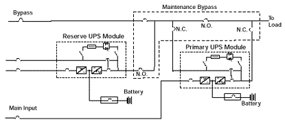
Isolated Redundancy. An alternate UPS configuration is an isolated redundant configuration as shown in Figure 4.
Isolated Redundant UPS
In this configuration, a "reserve" UPS module supplies the bypass input of the primary UPS device. In this way, protection against the primary module's failure is obtained. This is true when the primary bypass power is not available as well during periods of primary UPS module maintenance. However, a distinct disadvantage of isolated redundancy is the same as its strength: the fact the entire load resides on a primary UPS until the moment when it is needed most — i.e., at the point of power failure. This creates the potential for many risks. First and most obvious, the stand-by UPS must accept up to a 100% step load. Then, not only must the primary module's static bypass switches operate properly to obtain power from the reserve module, but also (should an output overload have occurred) both static switches must properly detect the situation and supply current from the utility source. Variations on the isolated redundancy configuration have included a single reserve module as backup to several independent primary UPSs. The reserve UPS generally is sized to support only one of the primary modules. This requires such complexity in the switch gear configurations and associated controls that it usually offsets any reliability gains.
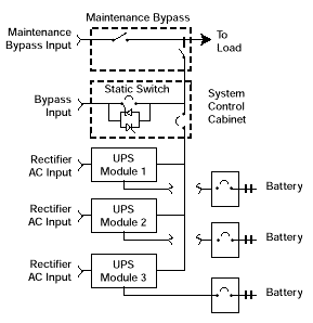
Parallel/Tied Systems. Another redundancy approach is the use of parallel redundant UPS modules with a static bypass switch as shown here.
Parallel Redundant (N+1) UPS
While this is the most widely applied approach, it does require careful application of the number of UPS modules and their configuration.
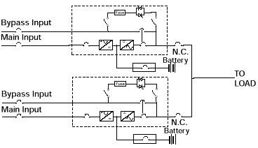
Principles of reliability dictate the fewer parallel modules required for the load capacity, the better. Consider that the calculated system MTBF of two parallel redundant modules is 2.27 million hours. The MTBF of the same UPS modules where three are used in the configuration drops to 757 thousand hours. When six of the same UPS modules are required with one module being redundant, the MTBF is reduced further to only 151 thousand hours. A variation of the parallel redundant system is the 1+1 configuration. As seen in this configuration, two single module UPS, each with an internal static switch, are connected in parallel.
(Back to top)
1+1 Parallel Redundant UPS
Some form of system-level control is still required to allow the modules to share the load and control transfers to the bypass source. Multiple static bypass switches must operate in parallel for proper reaction transfers and overload conditions. Further, system level maintenance bypass (which is not shown in Figure 6) is still required to do system level maintenance.
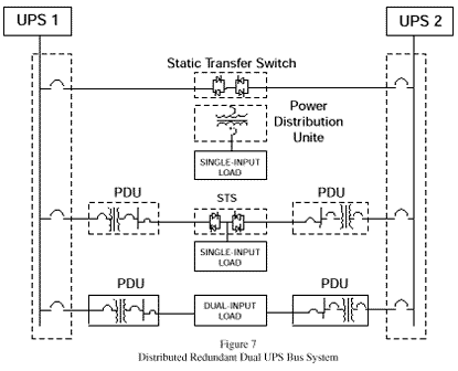
Distributed Redundancy. The distributed redundant configuration requires a complete change in the approach to large UPS design. This change in thinking is probably best reflected in a recent Uptime Institute survey of large data processing center downtime. According to survey results, 79% of electrical infrastructure failures that caused interruption of critical load operation occurred between the UPS output bus and the critical load. The emphasis of critical power system designers needs to shift from building a "bullet proof" UPS system to creating a fault-tolerant uninterruptible power of the UPS to the input terminals of the load equipment. This change in thinking is reflected in the following configuration:
Distributed Redundant Dual UPS Bus System
In its basic form, distributed redundancy involves creating dual, full capacity UPS system busses and redundant power distributed systems. This eliminates as many single points of failure as practical, all the way up to the load equipment's input terminals. In order to provide "fault tolerance," some method of allowing the load equipment to receive power from both UPS power busses must be provided. Protecting against fast power system failures, such as circuit breaker trips or a power system fault, requires a commensurably fast switching method. Static transfer switches (STSs) have been applied to accomplish very fast break-before-make transfers between two AC power sources. It is important that the two AC power sources be designed as independent as practical to eliminate any common failures. Switching between the two power sources needs to be break-before-make for the same reason. A number of distributed redundancy power distribution configurations can be devised. Keep in mind, however, that redundancy needs to be as close to the load as possible to achieve its goal — namely, keeping power available at the load equipment level. The ultimate distributed redundancy configuration would be two independent UPS power distribution systems with dual-input load equipment as redundant AC power is provided up to and inside the load equipment. Some may see the use of dual-input load equipment in this "ultimate" implementation as a drawback. After all, power system designers have little or no control over the selection or implementation of this type of load equipment. Remember, however, that more and more information technology equipment is being designed with dual-input capability. In this way, distributed redundancy not only provides the best assurance of power reliability and availability, but it also paves the way for an easy migration path as more dual-bus loads become deployed. (Back to top)
Distributed Redundancy: A Critical Part of the Business Plan
How can you determine if distributed redundancy is right for you? If high reliability, high availability and high probability of achieving the predicted MTBF are required, then redundancy — such as that found in the parallel redundant configuration — is a must. If loads are ultra-critical (i.e., you bought a very high MTBF/availability concept from your business equipment supplier) then the power system will need to be about 10 times more reliable than the load — and redundant — to avoid compromising the initial investment as well as the overall business plan. This almost certainly points to a distributed redundancy configuration.
Remember that facilities support systems cost nothing, just as critical loads cost nothing. Both are investments as opposed to overhead costs. This means they are expected to make money and to work to required levels within the business plan. The performance of the investment is the issue, not protection. Therefore, all components of the distributed redundancy configuration should be considered part of a performance package, not optional functions.
NOTE: You may obtain more information about distributed redundancy specific to your organization by calling Liebert Corporation, 1-800-877-9222; writing Liebert Corporation, 1050 Dearborn Drive, Columbus, OH 43229; or visiting the Liebert website: www.liebert.com. (Back to top)
The Components of Configuration: Some Basic Definitions
UPS: uninterruptible power supplies – a power conditioning and supply system that provides protection against short-term power outages.
Inverter: the DC to AC power converter driven by a UPS rectifier charger or battery via a DC bus. The inverter output drives the critical load, for example.
Bus: a communication channel to which devices connect; many of today's IS managers must deal with a mixture of single- and dual-bus input devices.
STS: a static transfer switch utilized to transfer between two sources of AC power close to the critical load.
PDU: a power distribution unit that manages and protects sensitive electronic loads.
About the Author
Robert Bauer is responsible for all strategic direction for the company's operations throughout the Americas. Prior to joining Liebert, Bauer held a number of executive positions within Emerson subsidiaries and strategic divisions.
About Liebert Corp.
Headquartered in Columbus, OH, Liebert Corporation is an independent subsidiary of Emerson Electric Co. Liebert offers the broadest range of products in the power protection industry, from simple surge protection and power conditioning to Uninterruptible Power Supplies (UPSs) in an array of sizes, configurations and topologies. Represented in more than 100 countries, Liebert products are widely used in network, telecommunications, and medical imaging and industrial automation applications. Frost & Sullivan reports that among UPS end users, Liebert is the leading manufacturer in brand recommendation and brand use among Fortune 1000 companies.
